 |
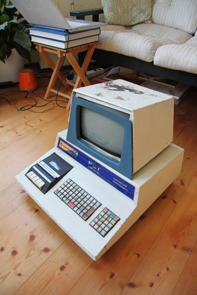
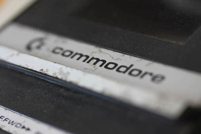
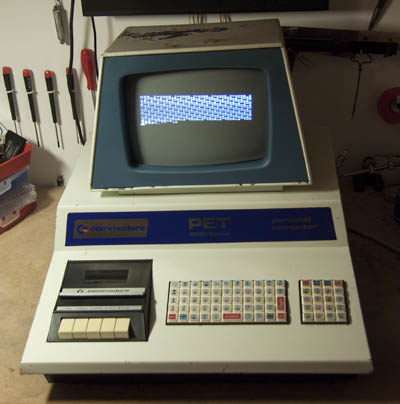
PET 2001 - 8 (Blue PET) in all its rusty glory!
I got this one relatively cheap from Ebay. Knowing it was not working. (only displaying one stuck character over the entire screen.)
On its way to me the parcel service did their part too ... now the metalcase of the monitor is heavily bent, the blue screen "mask" has luckily fallen off instead of breaking.
|
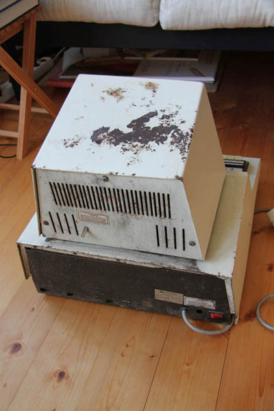 |
Rust - Rust - Rust ... |
 |
Looks like someone had burried this computer in his garden for the better part of the last 35 years. |
 |
Metalpart of the tapedeck. |
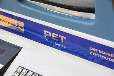 |
The blue label remained unbelievable clean |
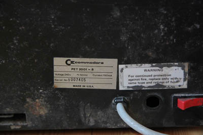 |
The fuseholder has been removed and the fuse is internaly shorted. |
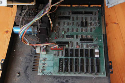 |
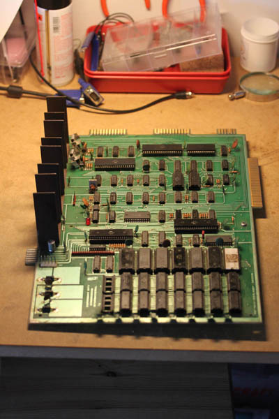
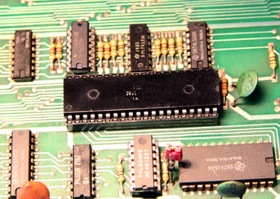
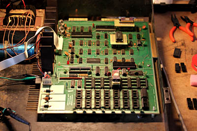
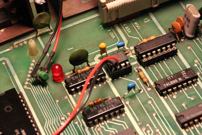
The first glimpse of the mainboard revealed a lot of dust and a few wrong things:
1) the CPU was inserted the wrong way around (all the chips should face to the right or the front! only the C8 PIA should face left)
2) 2 leftmost ramchips are missing
3) the rom chips were in a wrong order
|
 |
This is the correct order of the ROM´s for Basic 1 |
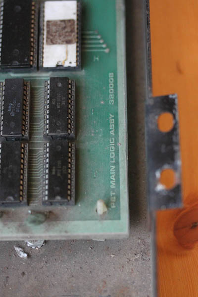 |
Closeup of the mainboard Number |
 |
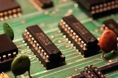
closeup of the roms (6540 type) and the rams (6550 type) here you can see the 2 leftmost ramchips missing ... i think the previous owner tried to swap them with the 2 video-ram chips |
 |
before cleaning and afterwards ... |
 |
after cleaning ... |
 |
I didn´t know if the PET would start with the 2 rams missing, but in the shematics (from zimmers.net) i found a jumper to configure the PET for 4Kb or 8Kb ... So i removed the jumperwire and replaced it with a "real" jumper ...
Didn´t help in the boot process => still one stuck character all over the screen ...
|
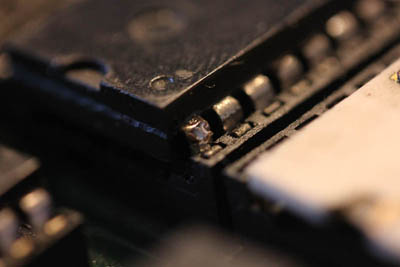 |
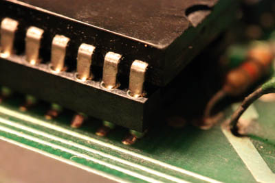
on one of the roms i found that a pin was brocken off!!!
after carefull replacement => no change
|
 |
Next i pulled out my oscilloscope and started to check a few things:
1) clean 5V on the leftmost Pin on all the 4 powerregulators (7805´s) OK! (i haven´t checked the right Pin´s as the 5V seemed OK! but we will come back to that later!!!!!!)
2) Clock Input on the CPU Pin 37 => OK!
3) Clock Output on CPU Pin 39 (phi2) => OK!
4) Reset Impuls on CPU Pin 40 => OK! (stays low after powerup for about 1 or 2 seconds and then goes high and stays high)
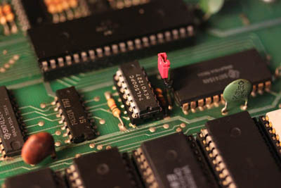
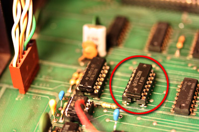
5) then i traced the phi2 clock to the romchips (should be on Pin 16 of the roms) => there was no Clock on the roms!!!! followings the signal from the cpu i found that G3 (a 74LS00 NAND) had a stuck to High output => i socketed and replaced G3 and voila => clock impuls on all roms.
|
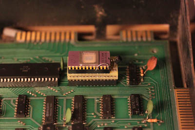 |
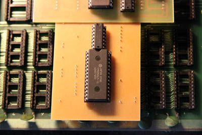
as the screen now displayed weird characters (depending on which rams i placed in the video ram sockets) i decided to replace the video rom, luckily the previous owner shipped the PET allready with an adapter he bought from 6540rom.com hoping it would cure the PET ... so i burned an eprom (the roms are available also at zimmers.net) and inserted the adapter in the video rom socket ...
=> the characters changed to "real" PETASCII characters
I found the 6540rom.com adapter had very short legs and very thin legs, so it didn´t make good contact in the infamous PET socket ... even a light touch on the adapter would change the characters on the screen ... and i didn´t want to solder the adpter to the mainboard (maybe i would need it to replace a System rom)
|
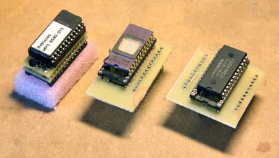 |
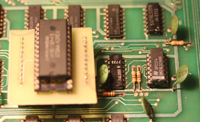
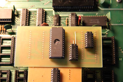
So i decided to build the Adapters from Nicolas Welte (www.x1541.de)
left: Adapter from 6540rom.com
middle: Nicolas Weltes video rom replacement (worked very well, now i get a screen full of real PETASCII characters)
right: Nicolas Weltes video ram replacement (not sure if my adapter works, because i get different characters with different 6116 Ramchips, maybe all of my 6116´s are broken one way or the other?)
Update: Now, running the testrom the video ram replacement works perfect, only 1 of my 6116 is broken)
|
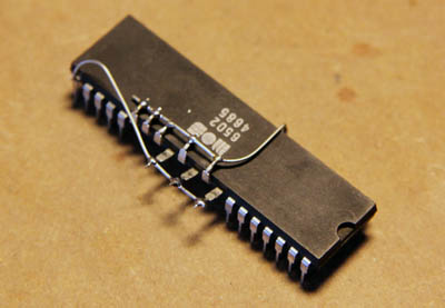 |
following a few topics on the vintage-computer.com forum i read about a NOP generator (a device that forces the CPU to execute endless NOP commands and in the meanwhile "count" thru all the adresslines => producing a steady pulsing on all the Addresspins.
So it is easy to follow the Address signals from the CPU thru divers buffers and logic chips ...
Some people build NOP generators using 40Pin sockets, but as i found enough 6502´s in my spareparts i bent up the necessary Pins and connected them tho ground or +5 using 2 wires
here you can find an instruction how to build a NOP generator for the 6502.
|
 |
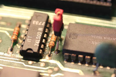
Using the NOP generator i found a defect 74LS17 Chip! after socketing and replacing the chip with a 74LS07 (the LS17 is not produced anymore, but the LS07 is a perfect replacement). all Addresslines to ram and rom seem OK. |
 |
while i was trying the Nicolas Welte Video ram replacemet board (i found a broken trace and one bad solderjoint on my homebrewboard) i switched the PET off, i switched it on again and now i have no Display on the Screen at all !!!
First i thought the monitor (or a part of it) is gone
But then i measured Pin 1 of the Video connector on the Motherboard and it is stuck High!!!
To have more Space to work, i decided to remove the Monitor to have easier access to the mainboard. To do that i had to open the monitor backside to disconnect the Power and signal cable
As you can see the dust didn´t bother to enter the monitor case ...
|
 |
To start from the "beginning" i measured the voltages on the 4 powerregulators again.
5V on all the left pins
BUT this time i measured the left Pins also and i found them to be 14V !!!!! which is twice as much as they should read ... thanks to MikeS from vintage-computer.com forum
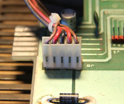
i started to measure around the Powerconnector
left to right:
14V AC, 14V DC, Ground, 14V DC, 7V AC
and the Transformer ...
|
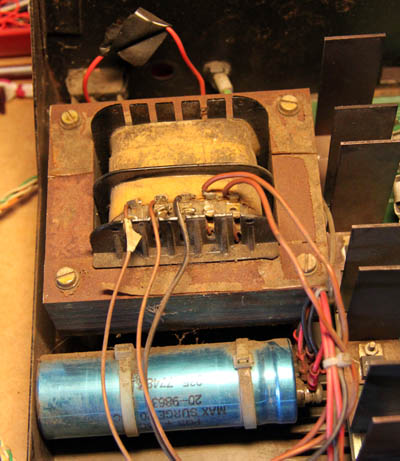 |
on the tranformer i measured the following:
Pin 1 leftmost brownwire to "ground" (black wire): 14V AC
Pin 2 2nd brown wire to "ground": 7V AC
Pin 4 to Pin 5 (power for Monitor): 14V AC
The red wires go to and come from the big blue "smoothing" capacitor ...
Now i figure someone has accidently switched the second brown wire with the black wire!!!!!!! as both of the brown wires should carry symmetrical 7V AC ... POOR PET !!!
|
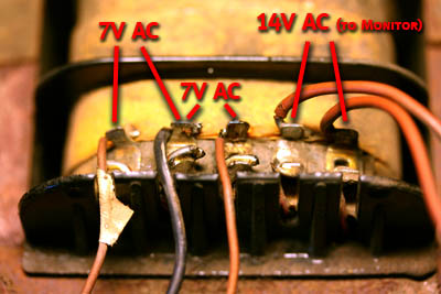 |
I have changed the wires on the transformer and now i have 7V AC, 7V AC and 14 AC (for the monitor which has a 7812 to bring the 14V AC to 12V DC)
The left picture shows the correct wire-order and the corresponding voltage readings.
The 4 x 7805 on the motherboard are now running very cool (only around 8V input voltage instead of 14V ...)
Still no Video Signal on Pin 1 of the Monitor connector (Static High), but i have VSync and Hsync ...
|
 |
Working my way back from the stuck High Video Pin, i found that C1 (74LS74) had a defect output => i piggybacked another 74LS74 ontop and i got a signal on the Videopin!!!!!
=> C1 socketed and replaced
|
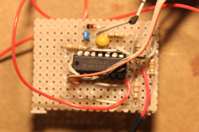 |
I build this small PET Videoadaptor, so i don´t have to use the original PET monitor.
With this adaptor i can connect the PET to my Philipps CM8833 (Amiga Monitor)
|
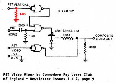 |
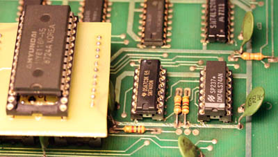
At first i got no stable picture, i poked around with my osci and i recognized, that the Vsync Signal did not go down to 0V only to about 1V, and the NAND Gate (which in this circuit works as a NOT) was outputing a steady LOW ...
after inserting the red resistor everything worked fine ...
|
 |
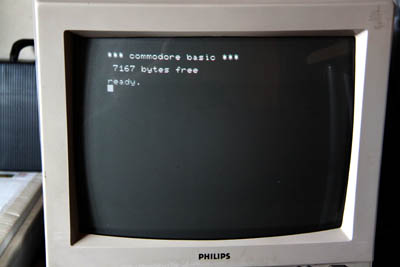
So here is what i get on the screen ... |
 |
i think the CPU only starts 1 out of 10 times at powerup, then i get pulses on the addresslines and on the datalines ...
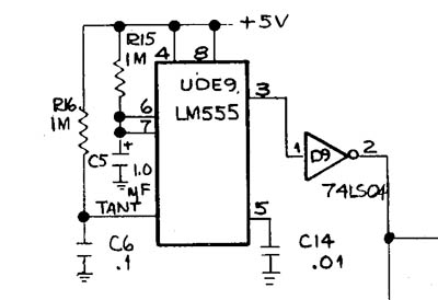
maybe some fault in the Reset circuit? (a 555 chip, a few capacitors, a NOT and a Bufferchip)
Signal on the 555 is going LOW after 2 seconds, the NOT is going High and the Signal is staying high but with a slight "noise" The Bufferchip is the one i have allready replaced (E4 a 74LS07)
will check this thoroughly later ...
|
 |
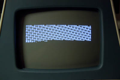
I did not find out how a PET 2001 should react if different chips are pulled out.
So here is my list you can remove:
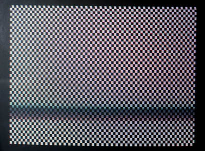
1) Only VIDEO RAM removed => checkerboard
2) CPU, PIA1, PIA2, VIA, RAM and VIDEO RAM all together and you will still get the checkerboard screen!
3) Only if you remove the Character ROM you will get a blank screen!
This may be helpfull in future repairs ...
|
 |
i removed all ROM´s and all but 2 RAM´s (i found out later, that the testprogramm runs even will all the RAM removed!) and burned Eudimorphodons PETTESTER ROM, using the 6540 Adaptor in H4.
after a few powerups i got the test running!
(as you see i had to remove one PIA or else the testprogramm would not display the uppercase characters but instead duplicates the graphicelements and the ramtest prints b´s)
|
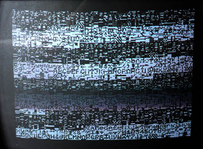 |
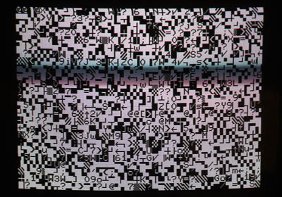
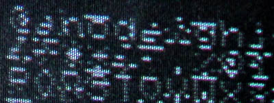
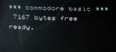
Here is the output of the Pettestprogramm, this screen is alternating with the following picture
As you can see (or maybe not :-)) the characterset (even with uppercase) is displayed 4 times.
BUT there are a lot of "noise" lines blinking and disturbing the picture ...
|
 |
Here is a closeup of the upper left screen corner |
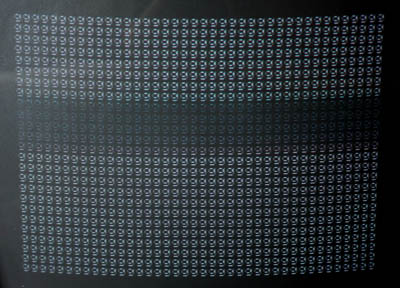 |
output of the ramtest ...
(no noise lines or blinking on that !?!)
(i think g is for "good" and "b" for bad, as i get "b´s" when i insert the second PIA)
|
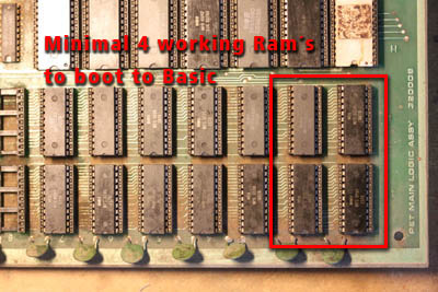 |
I checked all Ram chips => only 6 of them displayed "g" and only 2 of them work in the video ram sockets (with exactly the same picture as the video ram replacement board, so i figure the Replacement works fine!)
=> So i only have 2 really working RAM´s ...
(MikeS wrote, that you need atleast 4 (the 4 rightmost sockets) to boot into Basic ...
|
 |
while i was "probing" for the error in the Videosignal, i found C2 had one stuck high Pin => socketed and replaced.
It doesn´t change anything regarding the noisy screen.
|
 |
I build this small reset-switch (simply connects Pin 1 (ground) with Pin 2 of the 555 Resettimer.
The PET reseted only every n´th time (like on a "normal" poweron)
BUT then i removed the last 2 Ramchips and voila! powerup and reset works fine!
=> So i figure the two "good" rams aren´t so "good" at all and mess up the the Data or the Addressbus ... or maybe one of the Busbuffers is faulty?
|
 |
Oh no, i was to fast, to say that powerup and reset works (without ram) ...
Still only starts every n´th time ...
I replaced the complete reset circuit: 555 socketed +replaced, Tantal capacitor 1uf (yellow) and the 2 capacitors 103 and 104 (blue)
Still only starts every n´th time ...!!!!!!
|
 |
I socketed + replaced all 6 Bufferchips (74ls244)
No change in picture or start ...
|
 |
I replaced the CPU socket with a precission socket
No change in picture or start ...
|
 |
I thought maybe the startup/reset thing has to do something with the power ...
So i replaced all 4 47uF electrolytic capacitor
No change in picture or start ...
|
 |
Next i replaced the mainmemory with a 6264er Ramchip. Many thanks to Donni of VCF for mailing me his original design.
You can download a printable Version for etching here: Pet_ram_replacement
Now i got "g´s" in the Ramtest ... :-)
|
 |
Then i built a rom replacement board. This design also comes from Donni of VCF. Many thanks again.
You can download a printable Version for etching and a matching Romfile here: Pet_rom_replacement
|
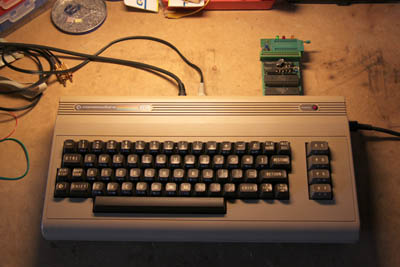 |
Here is my trusty C64 with the Quickbyte Epromburner ...
The nice grandson is helping his grandfather ...
|
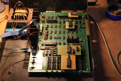 |
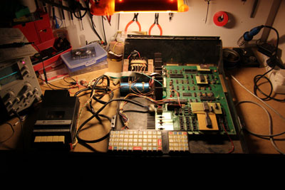
That´s what it looks like with all the boards inserted ... |
 |
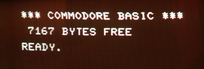
Eureka!!!!!!!
But no cursor, because of missing PIA´s
|
 |
Just out of curiosity i inserted the 2 (previously found dead) 6520´s and ...
Even the 6520´s that seemed to be dead work again !?!?!?
Startscreen with blinking cursor and no noise!
Eureka again!!!!
|
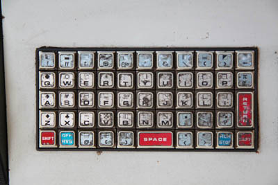 |
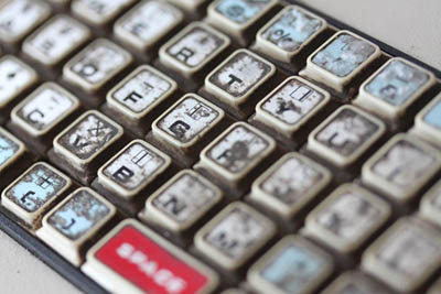
Before i try to type anything, i need to clean the keyboard. |
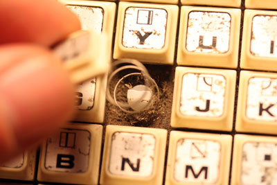 |
There are springs and a lot of dust under the keycaps. |
 |
I cleaned the contacts on the pcb and i washed all plastic parts with a mild but very good plasticcleaner. |
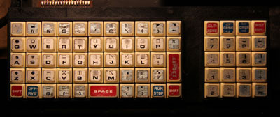 |
All keys are working! |
 |
Now i recognized, that the PET was always displaying lowercase characters (see a few pictures above!). After changing the 6522 i got a proper uppercase bootscreen. |
 |
Now i cleaned the tapedrive and replaced the belt.
I loaded space invaders (a .prg file) from zimmers.net and transfered it via the soundcard of my notebook to tape using a little program named wavprg. I used the invert waveform setting and maximum volume.
|
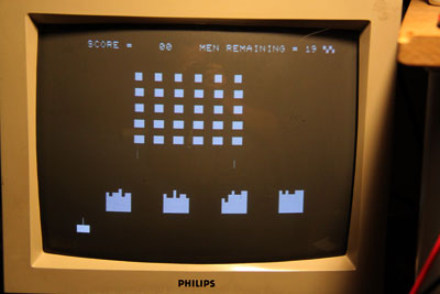 |
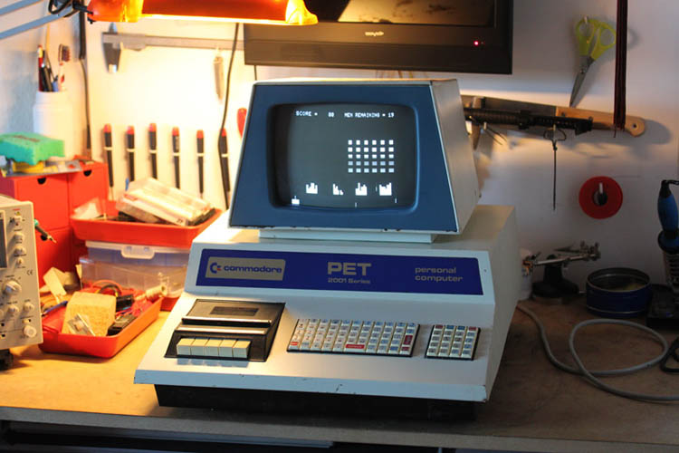
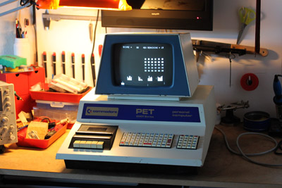
Here is me playing (rather badly!) space invaders! |
 |
After a bit of cleaning and bending the distorted metalparts into shape (hitting it repeatedly with a big hammer ;-)) |
 |
The picture is half the height as it should be ...
if i turn the little poti inside the monitor the picture gets a little higher, but very distorted and still not the full height ...
|
 |
I found D8 had a noise on Pin 11 (vertical drive)
(=> thats why i had to insert the additional resistor in the PET - Video adaptor!!)
Socketed / replaced => Picture now full height!
|
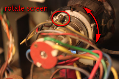 |
On the following pictures you find how to adjust the monitor ... Danger! High Voltage! only for trained technicians ...
Open screw and turn to rotate the picture
|
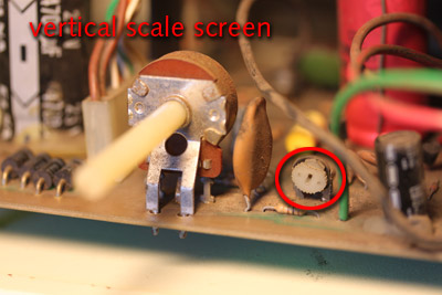 |
adjust poti for vertical scale |
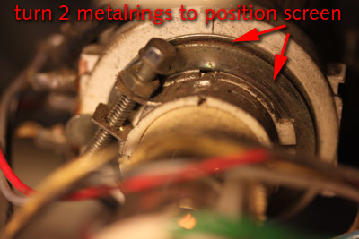 |
rotate the 2 metalrings to position / center the display |
 |
Finally ... (All that´s left to do is a little paintjob next summer ...)
:-)
|
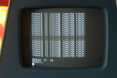 |
My thanks have to go to the guys at vintage computer forum:
especially: MikeS, Eudimorphodon and Donni
Thanks to www.6540rom.com and to Nicolas Welte for their great adaptors
The great resource at www.zimmers.net
Without their help this would have been impossible for me ...
THANKS!!!!
|